In PCB design, engineers often remain vigilant about signal integrity in high-speed circuits but tend to overlook impedance control for low-speed traces. When adjacent trace spacing exhibits irregular variations, even for non-high-speed signals, unexpected signal quality issues may arise. The impedance perturbations caused by spacing variations pose a greater threat than crosstalk and deserve heightened attention.
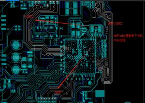
For digital interfaces with moderate speeds but strict timing/signal quality requirements (e.g., SDIO), trace spacing management remains critical.
If sufficient spacing (e.g., 3W rule compliance) can be achieved with GND isolation and adequate GND via placement, no significant compromises are needed. However, space constraints often force tradeoffs. In such cases, prioritize increasing critical trace spacing rather than blindly adding GND pours.
Why Avoid Arbitrary Copper Pouring Near High-Speed Traces?
For signals like 50Mbps or 100Mbps, we must evaluate whether adjacent trace spacing induces interference.
1. Basic Principles: 3W Rule and Extensions
- 3W Rule: The center-to-center spacing between adjacent signal lines should be ≥3 times the line width (W = trace width).
- Purpose: Reduces capacitive coupling by 70%~80%, suitable for low-to-medium speed signals (e.g., SDIO default mode at 25MHz).
- Limitations: Insufficient for high-frequency signals (≥50MHz) or scenarios with short rise times (<1ns).
Upgraded Solutions:
- 4W~5W Spacing: Applies to high-speed modes (50MHz~100MHz), further reducing crosstalk to acceptable levels.
- Guard Trace Isolation: Insert ground traces between sensitive signals (e.g., CLK). Spacing can be reduced to 2W but requires dense ground vias (spacing ≤ λ/10, ~15mm).
2. Spacing Recommendations for Different SDIO Modes
| SDIO Mode | Clock Frequency | Recommended Spacing | Additional Measures |
|---|---|---|---|
| Default Mode | ≤25MHz | ≥3W | No special requirements |
| High-Speed (HS) | 50MHz | ≥4W or 3W + Guard | Termination resistor (220~330Ω) |
| UHS-I Mode | 100MHz~200MHz | ≥5W or 4W + Guard | Impedance control, SI simulation |
| UHS-II/III Mode | >200MHz | Differential pairs | Strict reference plane shielding |
In our actual scenario, if we can only achieve 2W spacing, will there be crosstalk issues?
Compromise Strategies Under Space Constraints
- Priority Classification
- CLK signals: Mandatory 4W spacing or GND shielding.
- CMD signals: Secondary priority, ≥3W spacing.
- DAT0-DAT3: Prioritize intra-group length matching; tolerate localized 2.5W spacing between groups (requires SI verification)
- Local Density Adjustments
- Non-critical signals (e.g., CD detection) may use 2W spacing.
- Layer Sacrifice
- Route SDIO signals on a dedicated layer to avoid parallelism with other high-speed signals (e.g., DDR, USB).
Impedance Variation: A Greater Threat Than Crosstalk
If we fail to meet the 3W rule, and reduce the spacing to 2W instead, apart from the crosstalk issue, what other problems will arise?
When the PCB trace spacing cannot comply with the 3W rule (that is, the center distance of the lines is 3 times the line width), and can only adopt 2W, it will have a significant impact on signal integrity and EMI. The specific problems and countermeasures are as follows:
Increased Crosstalk
- Electric field coupling intensifies, raising crosstalk noise by 30%~50% (more pronounced in differential pairs).
- Near-end crosstalk (NEXT) in high-speed signals (e.g., PCIe Gen4+) may exceed specifications, elevating bit error rates.
Impedance Deviation
- Reduced differential pair spacing lowers differential impedance (typical drop: 5-10Ω), potentially exceeding ±10% tolerance limits.
- Single-ended trace spacing variations relative to reference planes increase reflections.
Elevated EMI Radiation
- Tight spacing amplifies common-mode current radiation. Imbalanced differential pairs may cause EMI to surpass FCC/CE compliance thresholds.
While crosstalk from 2W spacing has limited impact on sub-100MHz signals, impedance variations caused by spacing irregularities induce reflections and degrade signal quality. Optimizing spacing to 2.5W is recommended.